QBUS SYSTEMS AND OPTIONS
1. Qbus basics
by Ákos Varga
(Hamster)
1.1 The history of the qbus
1.2 The functionality of the qbus
1.2.1 Physical functions
1.2.2 Addressing basics
1.3 Qbus card types
1.4 Qbus backplane types
1.4.1 2 by X backplanes
1.4.2 4 by X backplanes
1.4.2.1 "Serpentine" configuration
1.4.2.2 QBUS/CD configuration
1.4.2.3 Mixed configuration backplanes
1.5 Qbus hints and tips
1.5.1 Device ordering
1.5.2 Working with qbus enclosures
Full Table of Contents
Note: These pages are for informational purposes, I cannot be
held responsible for damages, loss of information/hardware or injuries.
Take precautions, we're talking about sensitive equipment and electricity
here! I gathered the information from handbooks, catalogs, UseNet postings
and from my own experience, so I might be wrong here and there. Please
mail
me, if you find something that doesn't seem right!
1 Basics of the Digital qbus
1.1 The history of the qbus
The Digital qbus originates from the PDP-11 Unibus:
it was intended as the system interconnect for the low-end LSI (microprocessor-based)
PDP-11 microcomputers (its original designation was "LSI-11 bus"). It's
very similar to its predecessor, although it's simpler, and the throughput
is smaller (3.3 MB/s at its best). It was introduced in the PDP-11/03
computer with the LSI-11
processor in 1975. The first version was rather simple to the latest qbus
systems: the early implementation provided means for 18-bit addressing
(the above mentioned two processors used only 16-bit addresses), some connections
were used differently. Later qbus systems used 22-bit addressing, and different
techniques to access memory, which doesn't count as qbus traffic. From
now on, the name "qbus22", or "Q22" means qbus with 22-bit addressing capabilities.
1.2 The functionality of the qbus
1.2.1 Pysical functions
For those, who are new to Digital busses (or any busses for that matter):
the qbus is there to provide a way for the CPU (central processor unit,
the heart of the computer) to communicate with the memory and different
devices (peripheral controllers for example). Devices can use the qbus
to communicate with the CPU/memory or with another device, and it's the
processor's job to tell 'who' can use the bus for transferring data on
it (this is called arbitration). Every device issues a request, when it
needs to talk, the processor grants the right to do so according to multi-level
priorities (which are determined by a priority list and/or by the physical
distance of the device in question from the CPU) and the device becomes
bus
master. Some devices are able to transfer to and from the memory
without CPU intervention (DMA=Direct Memory Access; the CPU grants the
access to the memory, and from then the requesting device is responsible
for the further moves of data), mostly controllers that generate very much
traffic; this speeds up things. The qbus is an asynchronous interconnect,
there's no central timing sequence, the functionality of the system depends
on the proper use of request/grant/acknowledge signals (of course there
are timeouts to prohibit bus hangs).
Logically, the qbus is divided into the following parts: transmission
lines (for request/grant signals: data and address, system status), arbitrator
(which is normally in the CPU) and transmitters/receivers (which are on
the devices (boards) itself). Mechanically, the qbus consists of: the backplane
(slots
for the boards, interconnection between the connectors in the slots, lines
for the electrical power), the card-edge connectors on the qbus devices
(the connecting fingers look just like the ones on UNIBUS boards, sometimes
it can be confusing), and the signal termination on both ends. There's
no "motherboard" on the qbus as seen in the PC's for example: the bus
is just a physical way to interconnect system components, and the CPU is
just another device on it. The qbus is a "daisy-chain"-type bus, devices
are connected one after another. Basically, an empty slot between two qbus
devices means a break in the chain.
1.2.2 Addressing basics
The qbus, just like the UNIBUS, has memory mapped I/O addresses for
each device in the system, which means that they communicate through special
memory locations. Each device on the qbus has a device address, which is
referred as the Control and Status Register (CSR) address, and an
interrupt
vector. These values can be either fixed or floating addresses. Fixed
means, that there are address locations in memory for the addresses of
the particular option. E.g., there is a fixed address for the first device
of the kind, for the second, the third, etc. Devices of the same type must
use separate CSRs. A floating address is assigned a location within a range.
Sometimes the first device of a particular kind is at a fixed address,
and the next one is in the floating space.
As you will see, qbus addresses (both the CSR and the vector) are displayed
in octal values (the vectors are at the beginning of the qbus address space,
the CSR's are at the end). Physically, the addresses of a qbus device can
be set with jumpers or switches on the module. Modules with fixed addresses
and vectors are usually shipped with settings for the first device of that
particular kind. As the leading digits of an address are always the same,
and they're always at a byte boundary (1776xxxx0), only four digits
are configurable (this can be accomplished with 10 switches instead of
22). Vector addresses are often set by the opearting system upon boot.
Also, in manuals and by some system software, these addresses are only
referred to with six digits, i.e. 760215 is 177602150, or seven, i.e 7602150
is 177602150.
For example, the first MSCP (Digital's Mass Storage Control Protocol
- a protocol used with disk drives from te mid-80's) disk controller CSR
is at 772150, the other MSCP devices are in the floating CSR address space:
760334, 760340, 760344, etc...). The first TMSCP (which of course stands
for Tape MSCP) has its CSR at 774500, the second TMSCP device has a floating
CSR. On the other hand, the first Ethernet controller is at 774440, and
the next at another fixed location, namely 774460. Finding the possible
CSR and vector address values for a certain device is not trivial, but
the manuals can help. Also of great help is the SYSGEN
utility, which can be found on various Digital operating systems, e.g.
RSX11, RSTS, VMS.
1.3 Qbus card types
Something about the terminology used here:
-
A qbus module is a physical device, a card or board
by other names (a qbus card is usually a multi-layer printed circuit board
(PCB))
-
A qbus option is a device that interfaces to the qbus. An option
can consist of several modules and cableing/cabinet kit.
-
A qbus device is a qbus option by other name, which can provide
one or multiple services/devices to the whole system. A typical example
is a multi-function board, which can provide a console device (a serial
line usually), a line printer interface device and line-time clock. These
are three devices on one physical device. (A device can be of logical meaning
too, for example a DHV11 asynchronous serial line multiplexor can provide
8 serial devices to the operating system)
Dual-height card
Figure 1: A dual-height qbus card
A dual card has two card-edge connecting "fingers". These two "fingers"
are enough to transmit and receive all qbus signals and power.
Quad-height card
Figure 2: A quad-height qbus card
The quad boards have four "fingers". Sometimes only the first two are
used, and the rest is just used to draw power and to "jumper" some lines
(connect one signal line, which ends at the connector to the next line,
which starts at another pin, this is necessary to have continuity: if some
lines are not jumpered through, the bus chain is broken, and the devices
physically behind cannot be used), sometimes the second two fingers
are used to form another, "private" bus (For example one device can be
spread onto more than one board, and the boards can communicate with each
other on these lines (This of course assumes that the backplane is not
normal qbus on this side!). We'll see examples for this, one thing's for
sure: there are different types of backplanes, one must pay attention when
moving around cards between different systems!).
Handles
"Normal" qbus cards (well... most of them) have small plastic handles
on the end of the bord, and/or small metal "hooks" that are used to hold
it in place and help at insertion or removal. But there are also so-called
S-handle boards, which have different fitment, and small blanking panels
on them. These are used in BA2xx, BA3xx, etc-series enclosures. Note: there
can be other differences between S-handle and normal qbus boards, but let's
not overrush it!
Multi-board devices
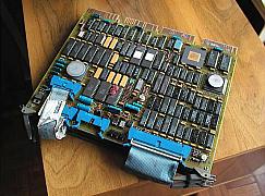
Picture 1: An option consisting of three quad-height boards, connected
to each other with ribbon cables
As mentioned earlier, some devices can occupy more qbus boards (mostly
2 or 3), sometimes these are connected with ribbon cables.
Grant continuity jumper card
This card can (must) be fitted into empty slots between two qbus devices
(we'll see reasons why can this occur), it jumpers the necessary lines
so that the remaining section of the qbus (on the farther side of the break,
seen from the processor's side) remains functional.
Qbus jumper
A jumper card (a set of two dual qbus cards connected with ribbon cables)
is used to connect two qbus backplanes. There are rules how to do this,
as the length of the qbus is limited.
1.4 Qbus backplane types
The backplane is the physical interconnect between the qbus devices
(boards). A normal qbus slot is dual-height (two "fingers" wide, or two
pysical slots), but most (apart from LSI-11 systems) backplanes are quad
height (2x2 "fingers"). There are two possibilities with this double width:
the second card insertion slot can be either another qbus slot, or it can
be used for some other purpose. From now on we'll be illustrating the backplane
from the card's insertion side, i.e. as seen when we insert a card. "Row
0" (the top) is seen with the component side of the cards upside.
           -------- --------
ROW 1     |   A    |   B    |
           -------- --------
ROW 2     |        |        |
           -------- --------
ROW 3     |        |        |
           -------- --------
ROW 4     |        |        |
           -----------------
Figure 3: A 2x4 slot qbus backplane (2 columns by 4 rows)
           -------- -------- -------- --------
ROW 1     |   A    |    B   |    C   |    D   |
           -------- -------- -------- --------
ROW 2     |        |        |        |        |
           -------- -------- -------- --------
ROW 3     |        |        |        |        |
           -------- -------- -------- --------
ROW 4     |        |        |        |        |
           ----------------- -------- --------
Figure 4: A 4x4 slot qbus backplane (4 columns by 4 rows)
1.4.1 2 by X backplanes
This is just like seen above (Fig.3). They're pretty straightforward,
as the "second two slots"-problem doesn't exist here. These backplanes
were mostly used in old LSI-11 and embedded LSI-11-based systems. Early
version are 18-bit, later ones are 22 (the conversion can be done easily,
so there could be backplanes with P/N's that suggest 18-bit, while they're
22...).
H9281-BA was one of the early LSI-11/2 backplanes by Digital (18-bit).
The -BB and -BC versions were 2x8 and 2x12 configurations with built-in
bus terminators.
1.4.2 4 by X backplanes
1.4.2.1 Serpentine configuration
The early 4x4 LSI11 backplanes had a "serpentine" slot configuration,
the cards must be ordered by this chain (and remember: no empty slots!).
Qbus Qbus
                 -------- --------       -------- --------
ROW 1           |   A    |    B   | --> |    C   |    D   | ---.
                 -------- --------       -------- --------     |
                 -------- --------       -------- --------     |
ROW 2      .--- |   A    |    B   | <-- |    C   |    D   | <--'
           |     -------- --------       -------- --------
           |     -------- --------       -------- --------
ROW 3      `--> |   A    |    B   | --> |    C   |    D   | --.
                 -------- --------       -------- --------    |
                                                              |
                                                    etc... <--'
Figure 5: "Serpentine" slot configuration
1.4.2.2 QBUS/CD configuration
Other backplanes (in newer enclosures, such as the BA2xx, BA3xx series)
have the so-called Q22/CD-style configuration), in which there are two
different bus columns: one is qbus straight downwards, the other is a private
interconnect. As this is used mostly in backplanes with 22-bit qbus, it's
called Q22/CD configuration (MicroPDP-11/83, MicroVAX3xxx systems use this).
Qbus C-D
                 -------- --------       -------- --------
ROW 1           |   A    |    B   |     |    C   |    D   |
                 -------- --------       -------- --------

                         |                       |
                         V                       V

                 -------- --------       -------- --------
ROW 2           |   A    |    B   |     |    C   |    D   |
                 -------- --------       -------- --------

                         |                       |
                         V                       V

                 -------- --------       -------- --------
ROW 3           |   A    |    B   |     |    C   |    D   |
                 -------- --------       -------- --------

                         |                       |
                         V                       V
                      etc...                   etc...
Figure 6: QBUS/CD backplane configuration
It's not trivial to use a backplane like this. The first thing: never
insert a dual-height qbus card into the C-D slot of such a backplane! Quad
cards are another problem. As mentioned earlier, there are different types
of them. There are cards that only draw power from the second two fingers,
which go into C-D. There's a chance, that card of this sort can be used
in such a backplane. Most quad boards don't have qbus connections on the
second two fingers, but they jumper the grant lines, which is why they
cannot go into a QBUS/CD backplane (or the jumper lines must be cut, you
must look at the qbus specs to find out how to do it). The cards intended
to be used in a BA2xx or BA3xx enclosure are designed
for this backplane configuration, these are the so-called "S-handle" boards.
1.4.2.3 Mixed serpentine / Q/CD configurations
This is something between the "serpentine" and the straight-down QBUS/CD
backplanes: the first few slots are Q22/CD, then everything's serpentine
downwards. Examples for this can be found in the BA23
(MicroPDP-11, MicroVAX I and II) and BA123 enclosures.
The BA23 has 3 Q22/CD and 6 Q22/Q22 rows, the BA123 is 4 Q22/CD and 8 Q22/Q22.
Qbus C-D
                 -------- --------       -------- --------
ROW 1           |   A    |    B   |     |    C   |    D   |
                 -------- --------       -------- --------

                         |                       |
                         V                       V

                 -------- --------       -------- --------
ROW 2           |   A    |    B   |     |    C   |    D   |
                 -------- --------       -------- --------

                         |                       |
                         V                       V

                 -------- --------       -------- --------
ROW 3           |   A    |    B   |     |    C   |    D   |
                 -------- --------       -------- --------

                         |
                         V
                 -------- --------       -------- --------
ROW 4           |   A    |    B   | --> |    C   |    D   | ---.
                 -------- --------       -------- --------     |
                 -------- --------       -------- --------     |
ROW 5      .--- |   A    |    B   | <-- |    C   |    D   | <--'
           |     -------- --------       -------- --------
           |     -------- --------       -------- --------
ROW 6      `--> |   A    |    B   | --> |    C   |    D   | --.
                 -------- --------       -------- --------    |
                                                              |
                                                    etc... <--'
Figure 7: A "mixed" backplane configuration (depicts the BA23 drawer)
In this case, only dual-height cards can be inserted into the left part
of the upper Q22/CD (if you don't have any, you must use grant continuity
card instead of normal cards), quad cards can go into the Q22/Q22 section.
To understand the existance of this configuration, you must know, that
the MicroPDP and MicroVAX systems which were shipped with this backplane
type, had non-qbus memory interconnects (PMI-Provate Memory Interconnect
for the PDP and LMI Local Memory Interconnect for the MicroVAX), which
use the C-D slot. These machines use the first slots for the CPU and memory,
everything comes after that - in the Q22/Q22 section.
4 by X qbus backplanes
H9270-A: 4x4 LSI11 backplane (18-bit), serpentine
H9270-Q: 4x4 Q22 backplane (22-bit), serpentine
H9273-A: 4x9 LSI11 backplane (18-bit), serpentine
H9275-A: 4x9 Q22 backplane (22-bit), serpentine, with built-in terminators
H9276-A: 9x4 Q22 backplane (22-bit)
1.5 Qbus hints and tips
1.5.1 Device ordering
You have to pay attention in which way you put your qbus cards into
the backplane. The positioning of a certain module depends on a couple
of things, like:
-
The function of the module: does it utilize DMA transfers? Is it sensible
to bus tiemouts? Are its buffers large enough to handle long bus latencies?
For example, a general DMA device, like the DRV11 can utilize many long
DMA transfers. You must now, that DMA grant priorities are given upon the
distance from the CPU: the nearest requesting device gets the bus. If such
a module is right next to the CPU, it will take up much of the bus cycles,
so the orher options will "starve".
-
Power: Some options (like the KDA50 disk controller) are real power-hogs,
which cannot be fitted into a densly occupied backplane without risking
power failures, burns, physical failure. These can be used in qbus expansion
cabinets, which have their own power supply.
-
The module itself: the old RQDX1 and RQDX2 disk controllers don't jumper
some of the qbus signals, so the rest of the backplane behind these modules
are useles. This cards must be fitted at the end of the chain.
We discussed the different backplane types above, now it's time to get
familiar with some rules of thumb:
-
The beginning of the bus is the CPU. Most CPU boards have built-in terminators,
so it's not very clever to fit them anywhere else.
-
Next to the CPU is the memory (this can mean multiple boards). You have
to pay attention when you're using CPU's with private memory. The best
example is the MicroPDP-11/83, which is a 18 MHz KDJ11-B CPU with PMI (private
memory interconnect) memory. In this case, the PMI memory boards are placed
before
the CPU board! (If you place them in the normal way, you get something
that some fo the operating systems identify as the "MicroPDP-11/73b")
If you're using a system like a MicroVAX II with LMI (Local Memory
Interconnect)
and qbus memory, you must place the LMI memory closer
to the CPU, the qbus memories come after them.
-
Communication controllers come most of the time at the begining of the
bus, especially high-speed asynchronous devices and network adapters need
this. Also, it's wise to place for async serial ports with no big buffers
(DLV11, DZV11, DZQ11), printer ports (LPV11) and general purpose I/O interfaces
here.
-
Async serial controllers (multiplexors), with DMA transfers and big buffers
(like the DHV11) are next.
-
The next items on the menu are tape controllers (TSV05, TQKxx).
-
Disk controllers are best served when placed at the end of the bus. As
I
mentioned, the RQDX1 and RQDX2 are always there. If you use an RQDXx with
drives in an expansion cabinet, the RQDXE adpaters come after them.
-
Qbus systems with unterminated backplanes must end with a terminator board
(for example a TEV11). Most terminators also have bootstrap ROMs on them,
sometimes even diagostics. There are also terminator boards with refresh
for the system memory RAM (REV11-C).
-
If you have multiple backplanes daisy-chained via qbus jumper cables, the
fashion is quite trivial: the first card of the jumper comes after the
last card in the first backplane, the second jumper card goes into the
first slot of the second backplane (pay attention to the configuration
(serpentine vs. Q/CD) of the second backplane!).
1.5.2 Working with qbus enclosures
These are just things that pop to my mind...
-
Qbus systems can be up to twenty-four years old now, keep that in mind!
Always check the power supply, fuses, cables, everything! Clean the connectors,
see after broken wiring, blown IC's, molten components on the boards. Accumulated
dust, spiderwebs, etc in these parts can lead to fire hazards!
-
The pins on the back of the backplane (old ones can have these, the newer
MicroVAX backplanes are implemented with printed board circuitry) for wire-wrapping.
Some versions of them could have been converted from 18-bit to 22-bit,
from serpentine configuration to something different, etc... The pins can
also bend togehther and short-circuit eachother: never apply power without
checking this, or you might blow the modules in the system!
-
Always double-check the configuration you've just compiled before powering
it up. Take a piece of paper, and write down the state of everything in
the computer enclosure (module ordering, strange observations (i.e. "there's
a quad LMI memory board in a Q22/Q22 slot"), before taking it apart - this
might seem trivial, but you forget so easily...
-
When reconfiguring a module, write down the original settings, you might
need them later!
-
Always make sure that the modules are properly in place! Some backplane
slot connectors can become stiff, you might have to push the modules to
their place with force, but take care! See what's be blocking the edge
connectors from sliding into the backplane. Caution: not all modules are
the same depth, one is shorter, the other one stratches out a bit...
-
It's quite rare, but I have seen qbus modules that have large components
on them that can touch the module above. If this large component is made
out of metal, it can cause a short circuit.
-
The cards should be in the side mounting slides, if not, they can bend
downwards from their own weight (or sideways, depending on the mounting
of the backplane), this can also cause shorts.
-
Some backplanes are very tight, so that you can't pull out a module from
between two others, don't force this, take one card after another, this
can save you some scratches and hand-injuries too.
-
"Hot swap" was never intended to work with qbus systems, always power down
the machine before making modifications, reconfiguring, adding or removing
modules!
-
If you want to use your qbus system on a 7x24 basis, make sure the enclosure
it's in is properly assembled: they function best with closed doors, back
panels, etc (cooling air circulation, noise sealing). Also make sure that
the power outlet is safe to use with a load like a fully packed LSI-11
or MicroVAX system can take (hard disk for example can consume quite some
power upon spin-up, which can blow the fuse).
If you have questions: Emailing me is perhaps not the best way to find
a solution you have with your qbus systems. The newsgroups vmsnet.pdp-11,
comp.sys.dec,
comp.sys.dec.micro
or alt.sys.pdp11 might suit better. To
use these links, you must have a newsserver configured, that sports these
groups. If you don't have access to one, try
dejanews!
Back to the top |